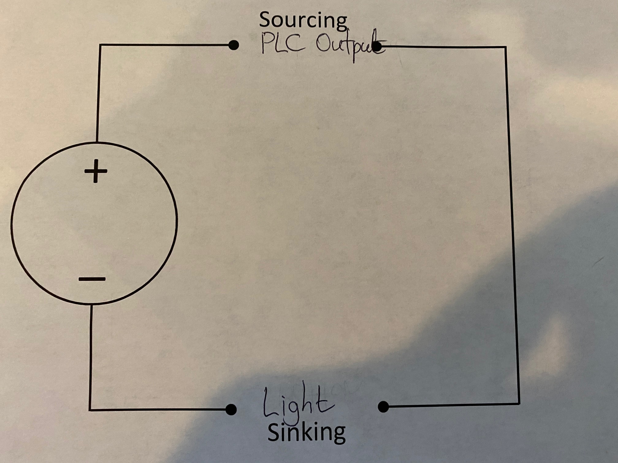
Wiring a simple output light

I am using a Micrologix 1100, part number 1763-L16BWA. I have been able to get the input side working, but can’t seem to figure out the output side. I also have an 1762-IQ8OW6 extension.

I have some simple lights that “light up” when I connect them to the DC + and DC- terminals so I know the lights work.

I have created a simple ladder program that has one rung for each output on the PLC and each output on the 1762-IQ8OW6 extension. Each rung has a separate bit that turns on or off that output:
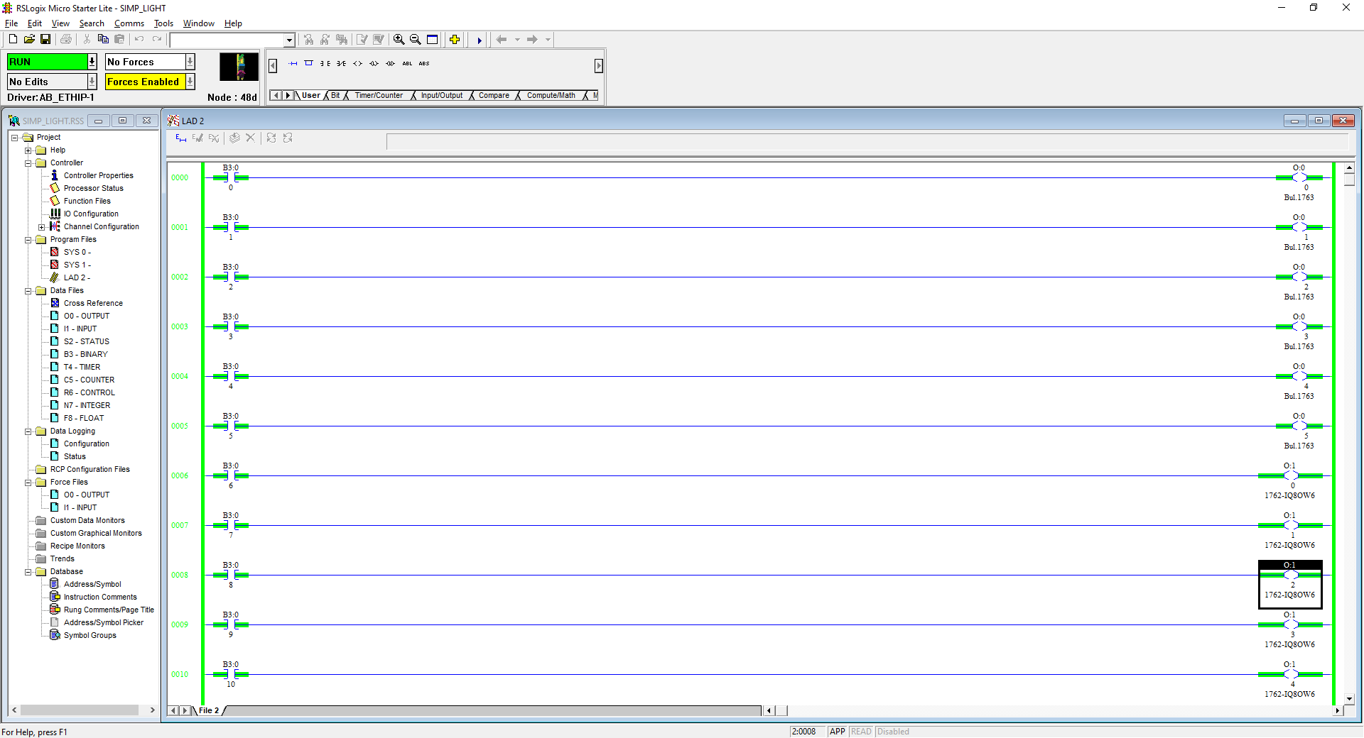
simple_light

All the outputs on the PLC and the extension are activated:
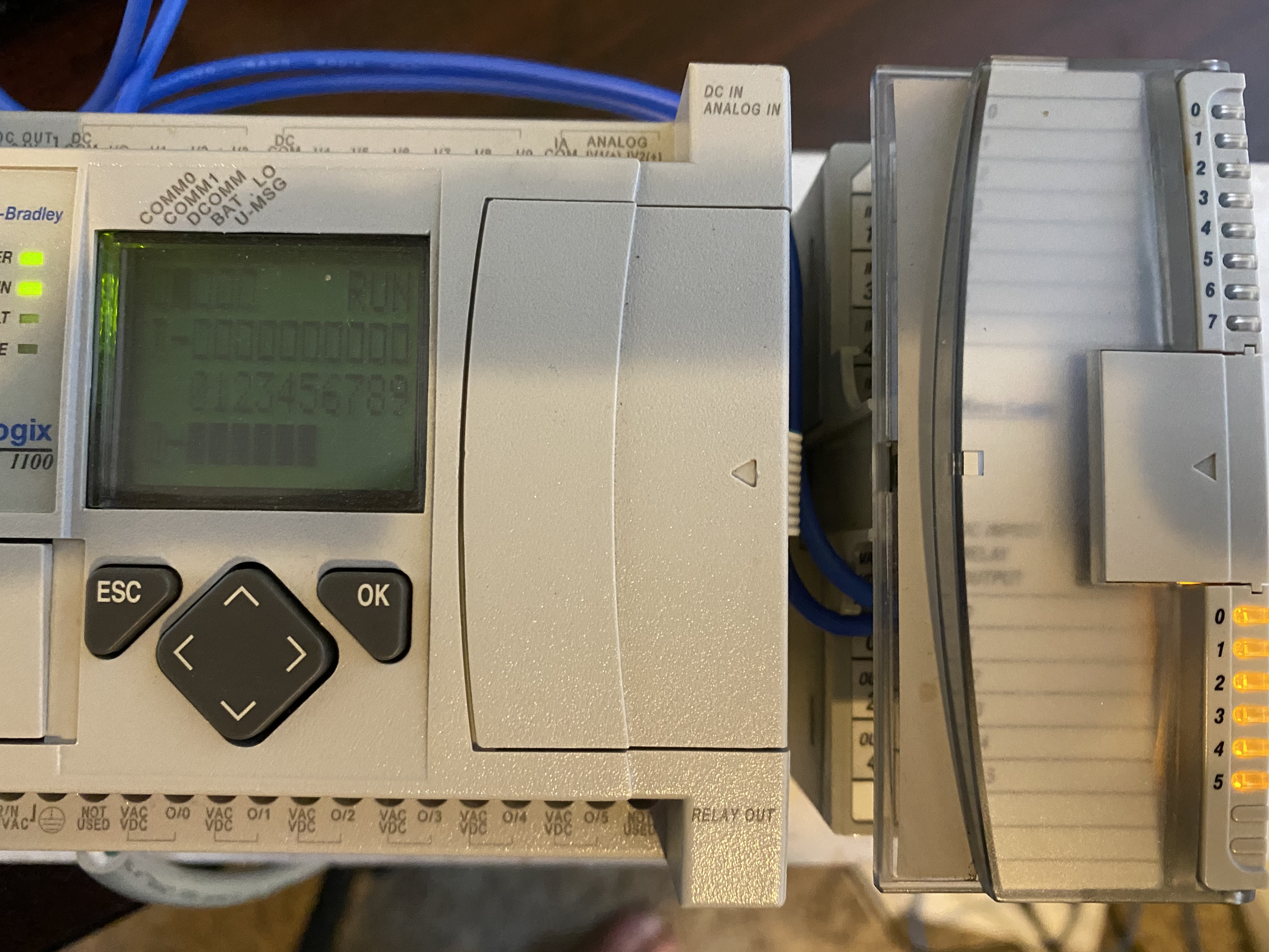
outputs_activated.jpg

However, no matter how I have tried to wire it, I can’t get the light to turn on through the output terminals. I have connected the VAC/VDC terminal in the output to DC+ and then connected one end of the light to the other output terminal and the other end of the light to DC-. I have tried the reverse.

I have tried wiring all 12 of the output terminals.

I have watched lots of videos, but they are all doing more complex things. It seems like everyone knows how to do this but me. :blush:

Please help.

Thanks.

In logic I see it well, since all the outputs and the lights indicate that it is working correctly.

From what I understand your light is 24VDC and if you test it directly to 24VDC it works.

The way you pose the connection seems to me as indicated:
VDC => + 24 VDC
Out => light end A

  • 24VDC => light end B

You could also connect the Out to -24 VDC and measure if indeed between the VDC and the OUT you have 24VDC before connecting the light.

Can you post a picture about how are you doing your hard wires? Thanks

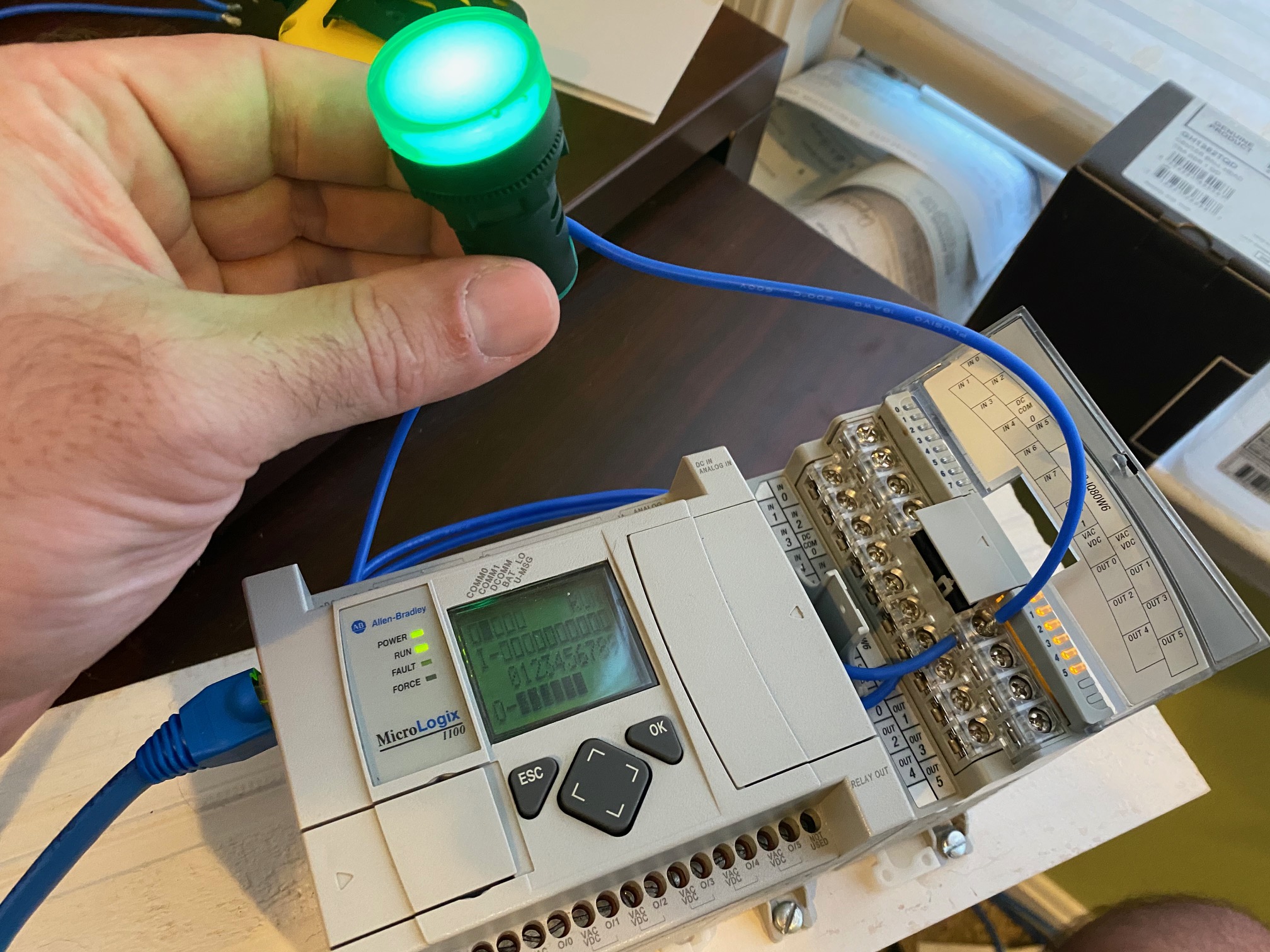
That’s right. In the below pic, I have connect DC+ to the VAC/VDC terminals in the 1762-IQ8OW6. I have also connected one end of the light to the DC- terminal. To get the light to work, I am just touching the other wire on the light to the screw of the VAC/VDC terminal.

This proves to me that the PLC is getting power and that all wires are functioning. It also proves the light is working.

light_on

If I understand things right, then I should be able to connect the open end of the light to any activated output terminal in the 1762-IQ8OW6. Since they are all activated, I should be able to connect the other end of the light to any output terminal on the 1762-IQ8OW6 to get it to work.

None of them are working so I am pretty sure I am missing something.

Surely.

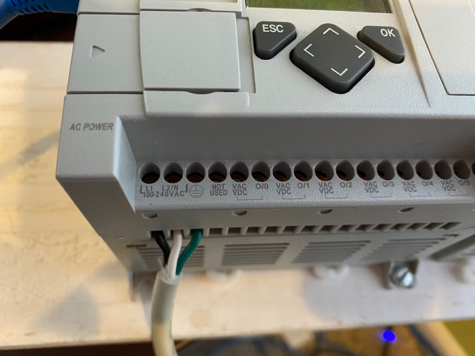
The power to the PLC is coming from a 110V AC plug.

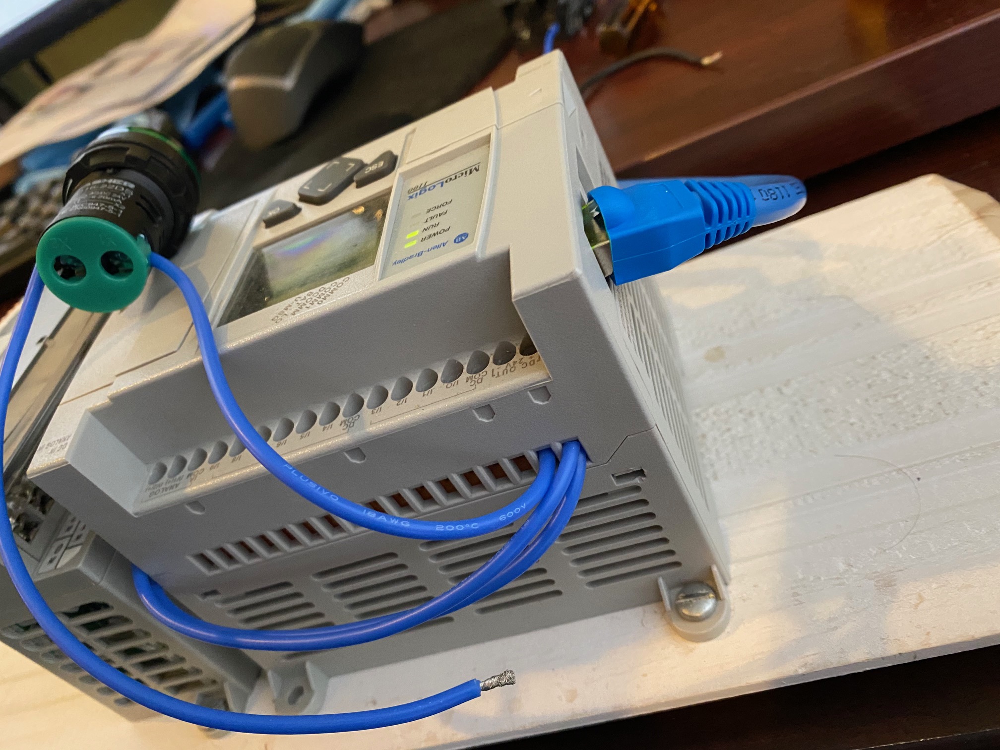
One end of the light is free so I can move it around and test against various terminals.
The other end is connected to DC-.

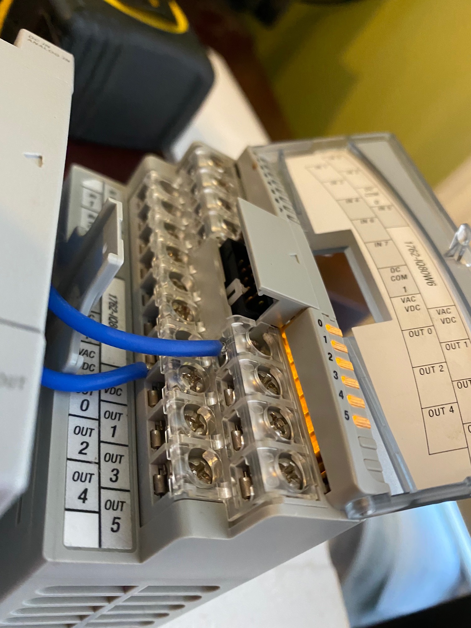
The DC+ output has two wires coming out of it. 1 wire is going to 1 VAC/VDC on the 1762-IQ8OW6 - the other wire is going to the second VAC/VDC terminal on the 1762-IQ8OW6. One of these terminals has 3 output terminals (0, 2 and 4). The other also has 3 output terminals (1, 3 and 5).

AC-Wiring
output-wiring
VAC-VDC

I tested a few of the 12 output terminals. I connected one end of a continuity test to VAC/VDC and the other end to the corresponding terminal and there was no continuity on any of them. I have reset the bit in the ladder logic program to turn the output on and off.

Am I doing something wrong on the PLC side? It seems very unlikely that all the Output terminals are not functioning - especially since all the input terminals work fine.

I can’t clearly see which terminals you’ve connected to on the photos, but the connection should be as follows:

  1. You bring in 24VDC into one side of the Output (there are two connections).
  2. You connect the output side to the + of the light.
  3. You connect the - side of the light to GND.

The output is just a relay; it provides no voltage on its own.

Can you post a basic drawing (in paint) of your connection?

Vlad

Vlad,

I am now thinking my relays are not working properly. I connect DC+ to VAC/VDC. I connect the other output terminal to the light. I connect the other side of the light to DC-. I have tested all 12 output terminals and none of them work. My lights don’t appear to have polarity. One end is marked X1 and the other is marked X2. Either way, I have switched the ends of the light on a few different terminals and get the same result.

Someone told me there should be a clicking when the relay engages or disengages and I am not hearing anything.

Have you ever had an 1100 repaired? Most places I have found want >$200 - seems steep when I can get another unit from ebay for less.

wiring-diagram

You should definitely hear a slight click as the relay engages/disengages. It’s really strange that none of them work though. What about your output card? Any issues with that?

In terms of repair, 200$ is definitely not worth it. As you mentioned, you can get a unit around the same price on eBay and make a claim if the outputs don’t work. I would look at it myself; if you’re comfortable with electronics, resoldering the relays shouldn’t be too complicated…

Do the lights that indicate the state of the output toggle when you toggle in logic? On the same note, I would use a simple multimeter to test the output. When it’s de-energized, you should read an infinite resistance and 0 when it’s energized. I’d definitely do that test with a multimeter before concluding it’s dead.

Vlad